In former photogrammetry much effort was spent into the development of highly precise and stable camera systems, which are known since decades. Similar concepts have also been applied, when analog imaging moved into digital. With the advent of unmanned aircraft vehicles (UAV) this concept changed, mostly due to the limited maximum take-off-mass (MTOM) of those systems. Typically an MTOM within 10kg should not be exceeded. This in a way prevents the use of stable, but also heavier and bulkier systems. This is, why regular consumer grade cameras are used quite often. Alternatively, manufactures combine their UAV-platform with proprietary cameras, which are often optimized for taking video sequences. Still, such commercial and quite low-cost UAVs increasingly are used for photogrammetric surveys. As an example the dji products of the Phantom or Inspire series could be mentioned, which have been established to map 3D structures of limited size. The wide distribution of such platforms is due to their easy use and attractive price. Many users, like engineering offices, who now have extended their terrestrial survey portfolio by UAV-based mapping, have invested in dji UAVs.
As the classical photogrammetry has its clear focus on the precise geometric modelling of 3D objects, the geometric calibration and stability is one important part of the process flow. From this point of view, almost all UAV camera systems belong to the group of "partially metric cameras" since the sensor matrix realizes a defined image coordinate system and the distortion parameters of the interior orientation can be assumed to be largely constant, while focal length and principal point position represent variable elements. From this, the necessity for camera calibration is obvious, which most often is carried out simultaneously within the bundle block adjustment of project data itself – this is called self- / or in-situ calibration, allowing the optimal estimation of camera calibration as part of the project itself.
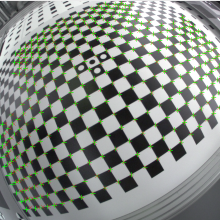
In order to analyze the potential of low cost UAV cameras, extensive tests have been made to estimate their geometric stability and performance. In order to have reproducible results most of these tests have been made in controlled laboratory environments. The Figure 1 shows the 3D test field for geometrically camera calibration in the photogrammetric lab at the Institute for Photogrammetry (ifp). Such test site allows for the precise estimation of geometric camera calibration parameters. If such (geometric) calibrations is done several time, where the individual calibration runs are spread over a longer period of time, the geometrical stability of the camera system can also be evaluated. As it can be seen from the Figure 1, additional Siemens star targets are distributed in addition to the coded targets. Such resolution targets are used to derive the true physical resolution of the sensor, which serves as an additional quality parameter of the camera system.
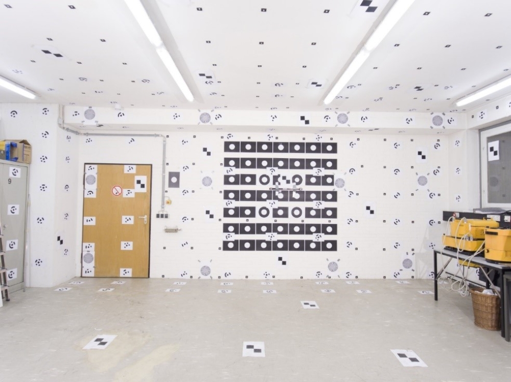
The Figure 2 now depicts the change of the principal point coordinates of different camera models. The three dji systems Phantom 4, Phantom 4pro, MAVIC are compared against the Nikon D800 DSLR with 35mm lens as the reference system. As you can see, the results from multiple calibration runs are illustrated. These tests have been made on several days, sometimes the systems additionally have been warmed up or cooled down to simulate different environmental conditions. In addition the calibrations have been done using the original camera raw images (converted to TIF) and the JPG images, as provided by the camera directly. Â Every graph shows a 4 x 6 pixel wide area, except for the MAVIC system. Here the variations in the principal point are much larger. Thus a 12 x 9 pixel wide area is depicted here.
It is surprising to see, that the Phantom 4 camera shows the smallest variations within the different calibration runs. Except one measurement, where the principal point coordinates are little more far away, all other results are within one large cluster, which clearly indicates a quite stable camera configuration. The reason for this is the stable concept of the Phantom 4 camera, with fix mounted and focused lens, which is close to the classic concept of metric cameras. Then the D800 shows the most stable behavior followed by the Phantom 4pro camera. As already mentioned, the MAVIC performs worse.
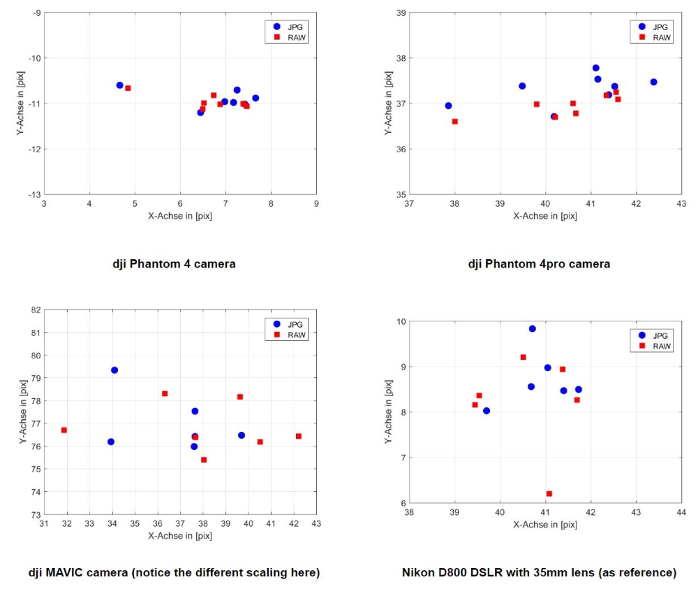
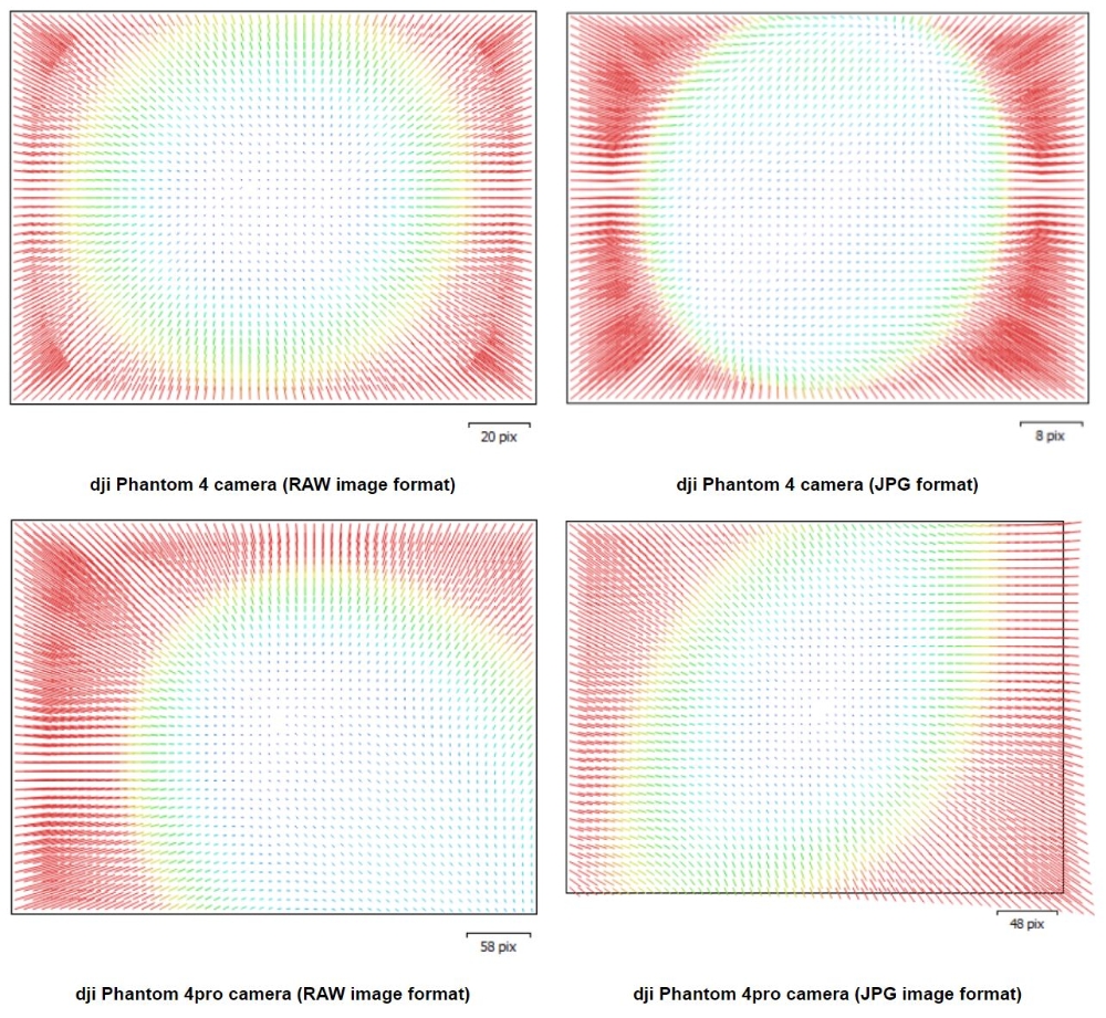
As it can be seen from the parallel use of RAW (converted into TIF) and JPG image formats, the selection of image formats also influences the results from calibration. In Figure 2 the estimated position of principal point differs depending on the use of RAW (blue) or JPG (red) image format. Obviously it is not only the (physical) image format which changes, internally the camera adds other corrections, when converting into JPG. This is also illustrated in the Figure 3, where the estimated lens distortion is shown for the Phantom 4 and Phantom 4pro camera. Again the results from using the RAW (converted to TIF) data are compared to the JPG images. It is quite obvious, that not only the image is converted to another data format, an additional a priori distortion correction is also applied, when changing formats their internal RAW to the JPG. When this pre-corrected image is not fulfilling the model of central perspective, this will influence the quality of later calibration. Thus, the use of uncompressed RAW image data is of advantage and should be recommended. Unfortunately most of the cameras need more time for the capturing of RAW image formats, which in a way limits the flights especially when high forward overlap is required and the flight speed cannot be decreased accordingly.
The a priori lab calibration of (UAV-based) camera systems in general is not necessary, as later empirical flights have been shown, that on-site camera parameters quite differ from the geometrical lab calibration. The calibration of the camera with the methods of in-situ or self-calibration is sufficient but only works if the block has sufficiently good block geometry. As a rule, all blocks with overlapping parallel flight lines or 360° circular image blocks with a large image overlap (the latter can be realized through copter flights) should fulfill these prerequisites. Possibly it is helpful not to start in-situ calibration from zero values, but to use the previous calibration as an approximation. Especially the distortion of the camera system changes little.
If unconventional block geometry (for example, individual flight lines for corridor applications) is present, a best pre-calibrated camera must be requested. Ideally, this camera is calibrated in a close temporal and spatial context nearby the mission area (i.e. by using a test area) and these parameters are then adopted. For such applications, cameras with the most stable camera geometry are preferred. In some circumstances, proprietary cameras, with fixed optics and fixed focus can be advantageous; alternatively specially developed (metric) cameras should be considered for these applications.
A sample QuickBird dataset is applied to test the relative orientation methods. The GSD of QuickBird data is 70cm and covering area is Melbourne, Australia. The original RPCs of the imagery are low accuracy. Figure 2 demonstrate the results before and after the relative orientation. Finally sub-pixel accuracy has been achieved in our work.

Michael Cramer
Dr.-Ing.Head of Research Group Photogrammetric Systems