The use of integrated GNSS/inertial systems is well-known and established in the traditional large-format airborne mapping since years. Recent commercially available unmanned aircraft systems (UAS) now also offer this technology, mostly reduced to the precise trajectory computation using differential GNSS for positioning. If one reduces the direct georeferencing to the control-point-free bundle adjustment, precise GNSS perspective centre coordinate computation will already solve this tasks for imaging blocks with several overlapping flight lines. The performance of such UAV-based image orientation and product generation without using any additional control points was analysed in a joint project together with the national mapping agency of Baden-Württemberg (LGL BW). The underlying application was the final survey of a re-designed rural road, which caused changes in the existing terrain. Final goad was the updating of the already available (laser-scanner based) DTM from multi-view stereo point clouds, derived from the UAV-images. Such image based dense point cloud generation using UAS platforms may offer an option to flexible map those changes almost immediately. With the use of directly measured GNSS (and/or GNSS/inertial) exterior orientations, such process might be solved very efficiently.
In order to analyze the performance of UAS-based direct georeferencing the area of interest was captured with the MAVinci Sirius Pro UAV (now Intel Corp.). This is one of those UAVs providing so-called RTK functionality, indicating that such systems have an integrated dual-frequency phase GNSS receiver with direct link to the base station. This allows for the precise real-time trajectory computation. The area was split into two blocks, flown with certain overlap in a flying height auf 125m above ground (GSD 3cm). Only two ground points have been made available to the flying company, one located in the eastern, the second in the western part of the test area. These points were used to set-up the GNSS reference station for real-time trajectory computation.
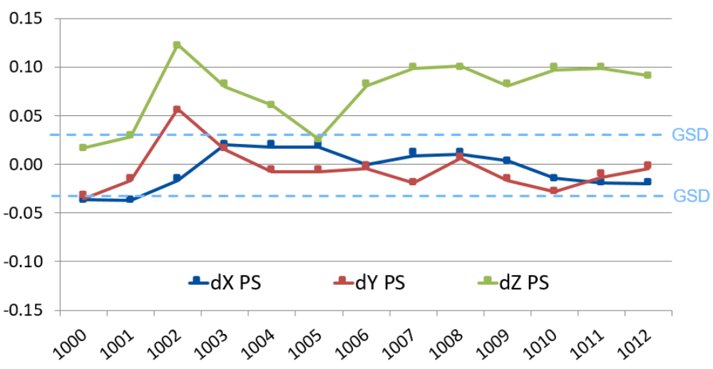
The quality of the delivered 3D object coordinates and DSM has been obtained from independent check point differences and reference DTM. The required 3D object point quality was better than <10cm. The Figure 1 shows the obtained individual check point differences from 13 check points. The maximum difference is within the vertical component. One of the 13 points shows larger error than 10cm. The vertical component seems to have a systematic offset in the range of 7.5 cm. Still, the required accuracy could be reached here (RMS 8.3cm). The horizontal difference is much smaller and stays within the 1 GSD level. In the vertical about 2.5 - 3 x GSD are reached.
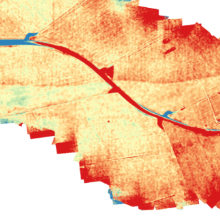
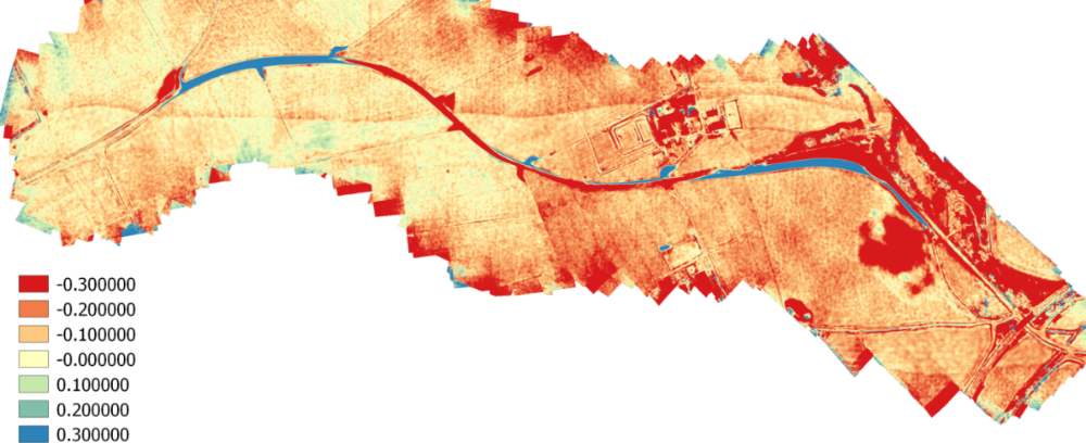
The area wide accuracy of surface determination can be obtained from the laser scanner reference DTM, processed from laser flights in 2002 (Figure 2). Since the two elevation data were recorded at different epochs – the laser DTM documents the state before the state road was re-build – the differences because of the change due to road construction are clearly visible. In addition, the difference elevation model naturally includes the system-immanent difference between the terrain surface (laser-DTM) and the visible surface (DSM from dense matching), especially for the areas that have (high rising) vegetation. The differences tend to be negative, which was expected, since here the surface model was subtracted from the "lower-height" terrain model (DSM minus DTM). These differences are in the range of -10 to -30 cm.
Especially a systematic difference between the two height models should be highlighted. There is a clear height jump which is across the region of interest, clearly visible in the central area of the study area and also in the south-eastern area. This is due to residual systematics from the strip adjustment of the former laser scanner data processing, which can now be revealed by the high accuracy of the photogrammetric surface model. Such effects are also known from other projects, where dense matched point clouds are compared to already existing (older) laser DTMs.
The empirical study has shown that RTK-UAS DTM update is possible, after reducing the visible surface to the underlying terrain by applying know filter processed to separate between surface and terrain points. The use of precise RTK perspective center coordinates is helpful for increased efficiency. The obtained accuracy fulfilled the requirements. The integration of the filtered UAS point cloud for the adaptation / updating of the existing DTM from traditional laser scanning worked sufficiently.
As it was shown, possible offsets in the vertical component might occur – already known from other GNSS-supported aerial triangulation projects. But only one single reference point would be enough to detect and correct for such systematic shift. As one drawback the small formats of UAV based images should be mentioned. When it comes to the manual verification of point clouds in stereo-viewing-mode, this is very cumbersome, due to the small area per models and thus the frequent model changes.

Michael Cramer
Dr.-Ing.Head of Research Group Photogrammetric Systems